Catalog C · Postwar · Special Feature · Book of Note
Firing of Rockets from Aircraft
Carl Anderson’s restricted wartime report, Caltech, 1946
At first glance this looks like a workmanlike piece of wartime ordnance literature: a restricted technical report in unglamorous red cloth, with no author’s name that means anything outside a citation index. It rewards a second look. Issued in 1946 by the California Institute of Technology under OSRD Contract OEMsr-418 and edited by Catherine Campbell, the report runs 138 pages of photographic plates and diagrams, its title and “RESTRICTED” stamped directly onto the boards in gilt.
Carl Anderson: A Physicist at War
Carl Anderson is Carl David Anderson: the Caltech physicist who discovered the positron in 1932 and shared the 1936 Nobel Prize in Physics for it, and who two years later, with his student Seth Neddermeyer, identified the particle that became known as the muon. When the war came, Anderson set that work aside and went into ordnance. By his own account, decades later, he was put in charge of adapting rockets, larger ones than the standard infantry types, for use on aircraft, which is precisely the subject of this volume.
The book’s own acknowledgements page confirms it in period language: Anderson “acted as supervisor” of the Aircraft Launcher Group under Contract OEMsr-418, directing a research staff of more than twenty. He wasn’t the sole author, either. William R. Smythe, the Caltech electromagnetism theorist whose textbook trained generations of physics graduate students, wrote Chapter 5 outright, and Leverett Davis, Jr. contributed several sections of Chapter 3. The “restricted” title page conceals not one but a small cluster of serious Caltech physicists, with a Nobel laureate running the project.
Section H: Caltech’s Other Rocket Program
The contract number tells its own story. OEMsr-418 was not the Guggenheim Aeronautical Laboratory’s better-known rocket program, the von Kármán–Malina–Parsons group that became the Jet Propulsion Laboratory. It was a separate Caltech effort, organized as Section H (later redesignated Section L) of Division 3 of the National Defense Research Committee, under the Office of Scientific Research and Development. Its founder was Charles C. Lauritsen, a Kellogg Radiation Laboratory physicist who had been working on proximity fuzes for the Navy before deciding, in September 1941, three months before Pearl Harbor, that the deeper problem was the rockets themselves, not their fuzing. He built a Caltech-based rocket ordnance program almost from scratch, drawing his core team from the Kellogg physics group: William Fowler, Bruce Sage, Ralph Smythe, Frederick Lindvall, Ira Bowen, and Anderson, with Earnest Watson handling administration. Over the course of the war this project designed and helped manufacture a lineage of aircraft and ship-launched rockets, including what became the HVAR and, eventually, Tiny Tim.
This report is a direct product of that effort. The DTIC catalog of OSRD Division 3 rocket-ordnance reports lists it as entry #1242, Firing of rockets from aircraft; launchers, sights, flight tests, with an origin date of August 1943 and a supplement that September, folded into a “final report” issued under OSRD 2549 in 1946. That gap between wartime origin and postwar compilation is typical of OSRD final reports, many of which were assembled and formally issued only after the program’s work was substantially complete.
The Illustration Program
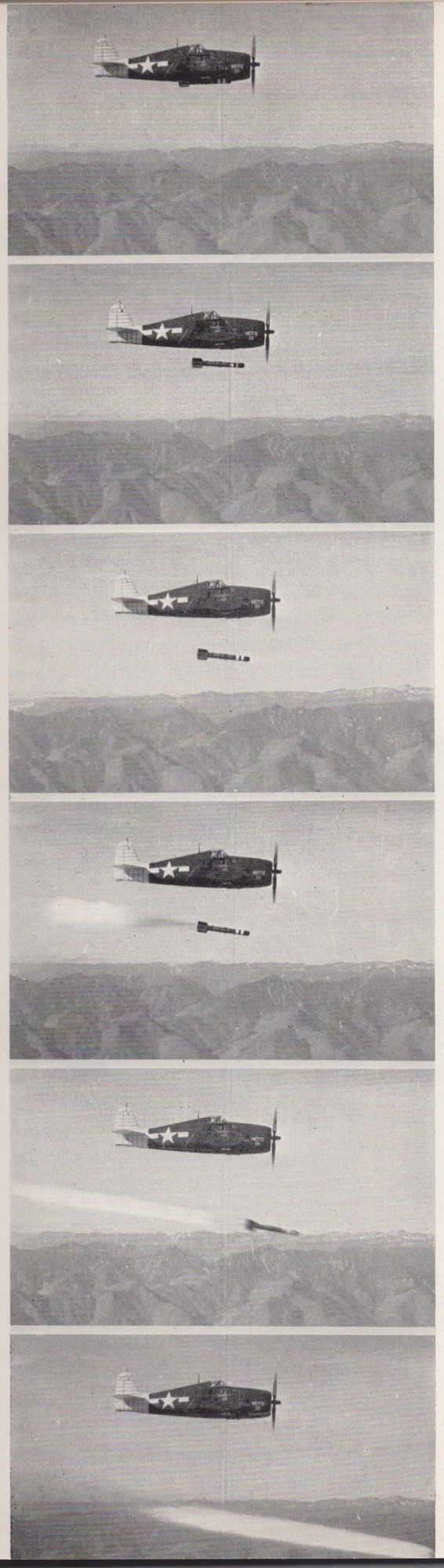
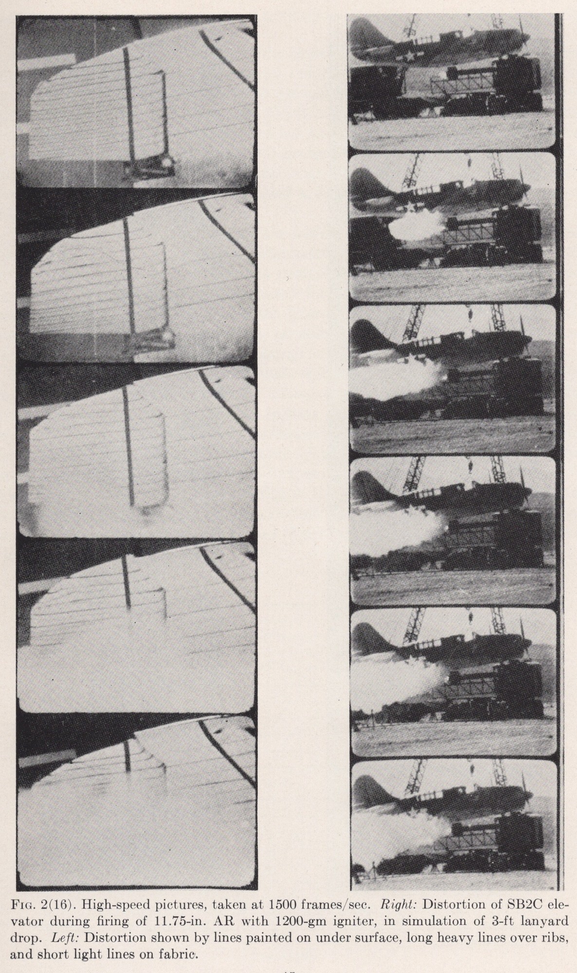
The illustration program is more ambitious than the plain binding suggests. The 138 pages carry several distinct kinds of photographic and diagrammatic evidence rather than routine ordnance snapshots. Sequential launch photography tracks individual rockets separating from the airframe across consecutive exposures: an 11.75-inch aircraft rocket dropping clear of an F6F Hellcat, frame by frame. Most striking is a sequence of high-speed photographs, taken at 1,500 frames per second, documenting blast-induced fabric and rib damage to an SB2C elevator during test firing, with reference lines painted on the control surface to measure distortion under load.
Six Aircraft, Three Calibers
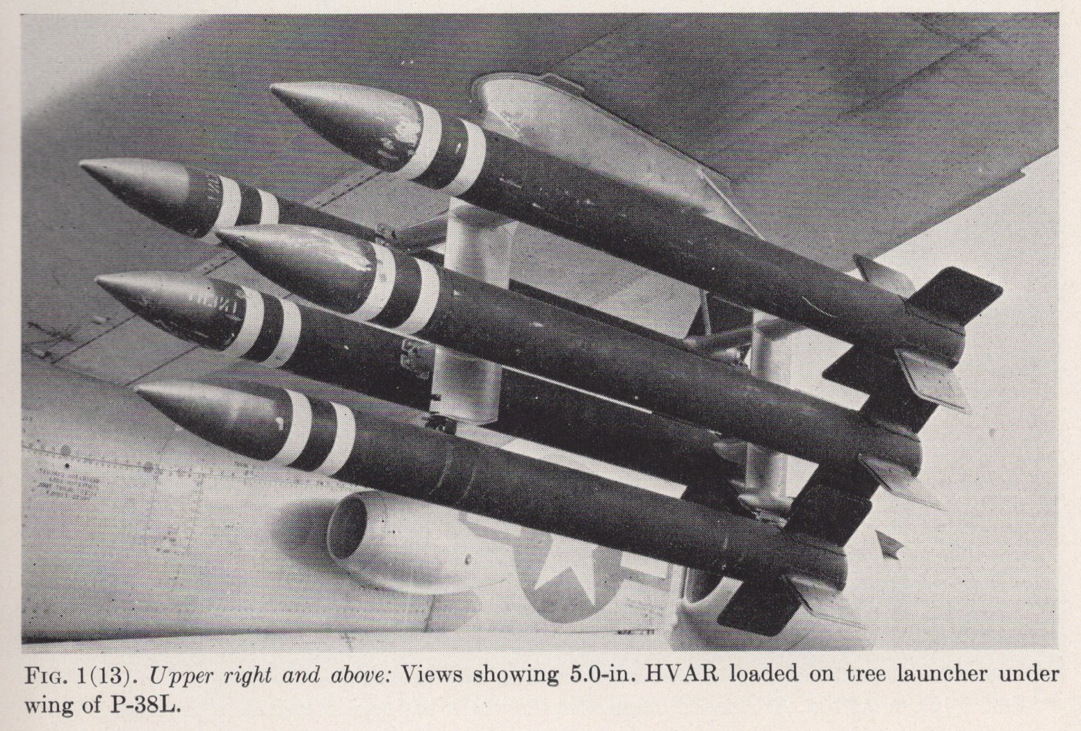
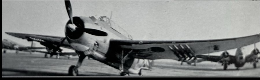
Coverage extends across at least six aircraft types (F6F, F4U, P-38L, PBY-5/5A, TBF, SB2C) and three rocket calibers (7.2-inch VAR, 11.75-inch AR, 5.0-inch HVAR), including retro-launcher installations on the TBF, ripple-salvo firing from the PBY-5A flying boat, and a tree-launcher fit of the 5.0-inch HVAR under a P-38L’s wing.
Computing the Sight
Paired with the ballistic sighting diagrams elsewhere in the volume, the report reads less like a parts manual and more like an applied physics investigation of a weapons system, which tracks with having a cloud-chamber experimentalist overseeing its documentation.
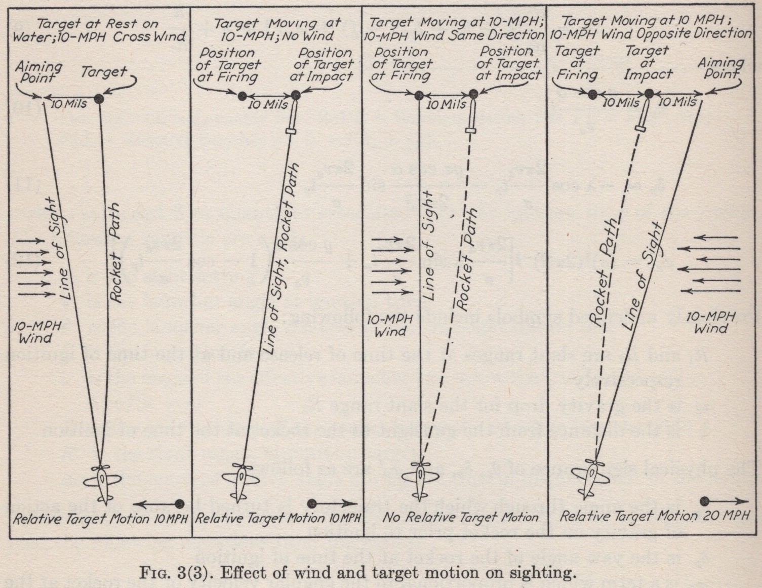
A rocket stays airborne for several times as long as a bullet fired at the same target, so wind drift and target motion throw off the aim proportionally more, the reason Anderson’s group needed a computing sight rather than an adapted gunsight. The four panels of Fig. 3(3) lay the problem out plainly: a stationary target in a crosswind, a moving target with no wind, and a moving target with the wind first helping and then working against it. Each case shifts the aiming point differently, exactly the kind of variable a sight built for bullets had no way to absorb. The schematic in Fig. 4(3), from the chapter on the CIT Type 3 Sight, shows the electromechanical solution: a voltage-balancing servo converting the sighting computation into the mechanical displacement of the reflector plate in the sight head.