Catalog F · NASA Missions · Special Feature
Training for Eagle
Two Grumman study guides keyed to LM-5, May 1969
Grumman’s internal numbering for the Lunar Module ran in build order, not mission order: LM-3 flew as Apollo 9’s Spider, LM-4 as Apollo 10’s Snoopy, and LM-5 as Apollo 11’s Eagle — the lander Neil Armstrong and Buzz Aldrin took to the Sea of Tranquility. Two Grumman training binders in the collection are keyed to LM-5 and dated the same month, May 1969: two months before Eagle flew, and issued right after Apollo 10’s LM-4 came back from its own dress-rehearsal flight around the Moon. One covers the Lunar Module’s Electrical Power Subsystem — the batteries, buses, and control assemblies that kept Eagle alive on the surface and got it back off again. The other covers its structure and its lunar-surface equipment — the airframe itself, the landing gear, and the gear astronauts would carry out onto the Moon. Every diagram in both is drawn from LM-5’s own configuration.
A Contractor’s Classroom, Not a Cockpit
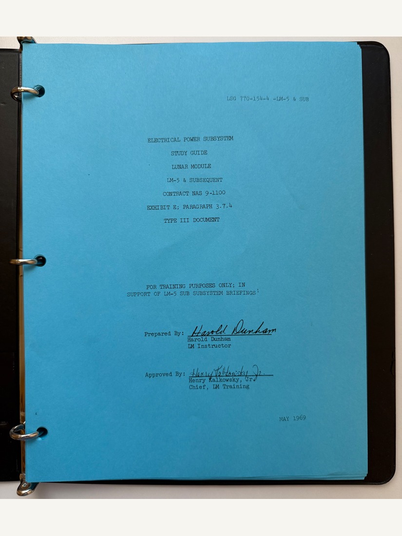
The title page places the guide precisely inside Grumman’s paperwork for NASA’s Lunar Module contract, NAS 9-1100: it is a “Type III document” under Exhibit E, Paragraph 3.7.4 of that contract, meaning a defined, lower tier of contract deliverable rather than a formally released engineering specification. Its stated purpose is narrow and explicit — “for training purposes only, in support of LM-5 SUB subsystem briefings” — and it was written not for the astronauts themselves but for whoever Grumman and NASA needed briefed on the Electrical Power Subsystem in the run-up to a flight: flight controllers, engineering staff, and quite possibly backup or support crew.
What “LM-5 & Subsequent” Actually Promises
The title’s second half is worth taking seriously rather than reading past. Grumman baselined its training material off whichever Lunar Module was next in the pipeline, then scoped it to cover that vehicle “and subsequent” ones too, so the same guide could keep serving Apollo 12’s LM-6 and beyond without a rewrite unless something in the hardware actually changed. NASA’s own Apollo Lunar Surface Journal preserves other examples of exactly this convention — a January 1969 Lunar Module Systems Handbook: LM-5 to LM-9, and later Grumman operations handbooks for “LM 10 and Subsequent” and “LM 11 and Subsequent” — so this guide’s scope is a known, documented pattern rather than an oddity. What that means here is that the connection to Apollo 11 is real and precisely dated — this is LM-5’s configuration, captured two months before LM-5 flew — but the guide was not written as an Apollo 11 keepsake, and it kept right on being used, unrevised, after Apollo 11 was already history.
Eagle’s Own Panels
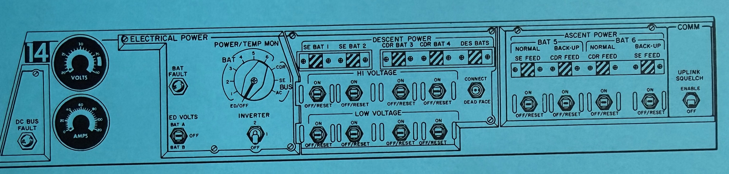
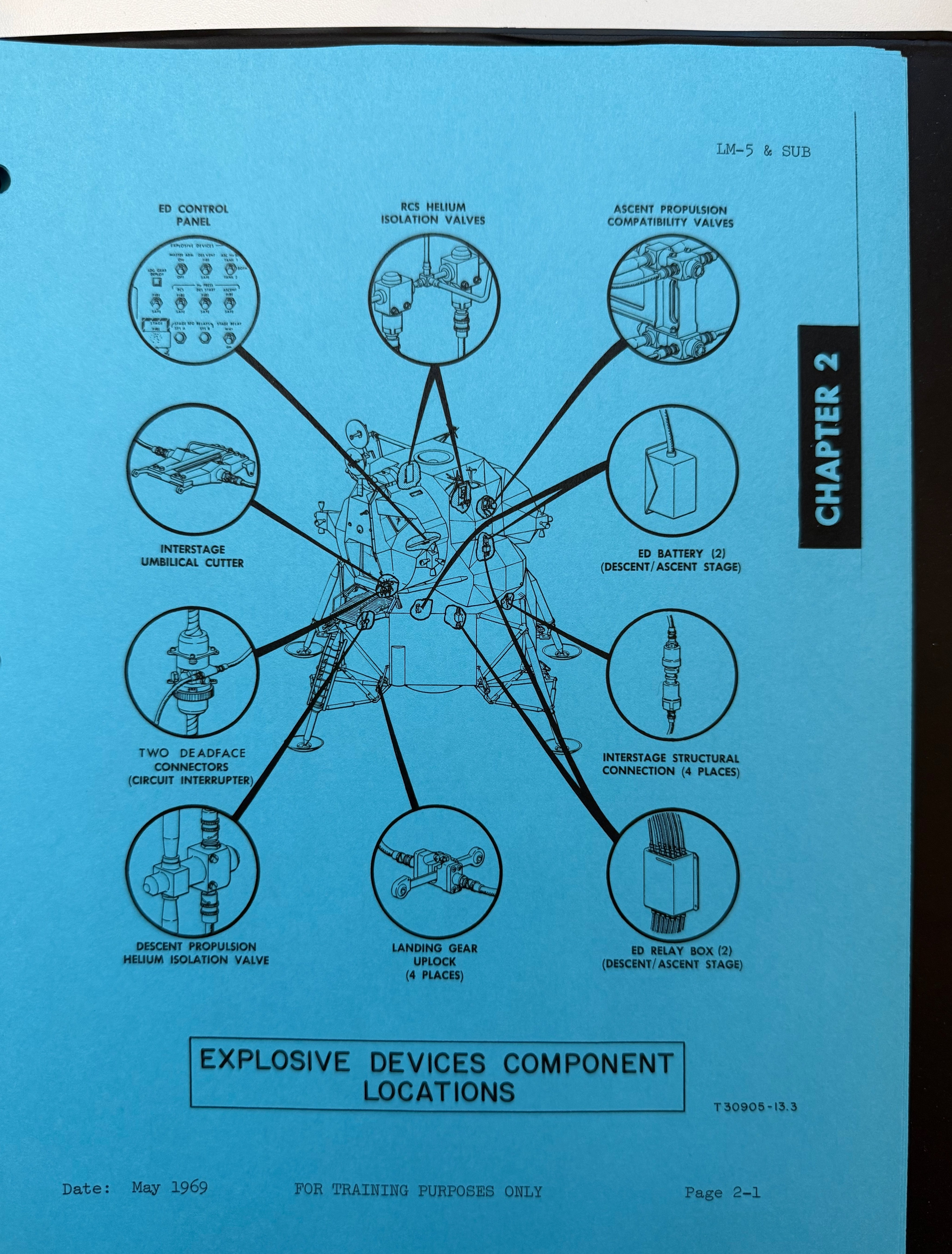
Three chapters cover the Electrical Power Subsystem end to end: the descent stage’s four batteries and the ascent stage’s two, each with its own Electrical Control Assembly; the DC bus architecture that let power be cross-tied between the Commander’s and Lunar Module Pilot’s sides, or fed in from the Command Module through the LM/CSM umbilical while docked; the Launch Umbilical Tower control logic that governed power hand-off in the last half hour before liftoff; and a table of the subsystem’s seven operating modes, from ground support equipment through transposition and docking, powered flight, and — last on the list — an aborted ascent. The diagrams reproduce Panels 11, 14, and 16 exactly as LM-5 carried them, switch labels, meter faces, and all, alongside the Explosive Devices Subsystem (staging and abort hardware, keyed to LM-5’s Panel 8) and the Lighting subsystem, down to the tracking- and docking-light specifications that would have mattered most during Eagle’s rendezvous with Columbia after leaving the surface.
A Lunar Module electrical training guide, dated just before the summer of 1969, keyed specifically to LM-5: too precisely dated to be a coincidence. It is not. LM-5 is Eagle, and this is a small, honest piece of the machinery — Grumman’s own contractor training apparatus — that stood behind the vehicle for two months before it became the first crewed spacecraft to land on the Moon.
A Second Handout, the Same Two Months
A second Grumman binder in the collection, LSG 770-154-10 – LM-5, is dated the same month as the Electrical Power Subsystem guide and approved by the same LM Training office, though prepared by different instructors. It names a more specific audience than the first guide does: it is addressed, in so many words, “for Flight Control Division at MSC, Houston, Texas.” Its title drops the “& Subsequent” qualifier too, reading simply “LM-5” — a difference too small to read much into on its own, but consistent with a document written for one flight-control briefing rather than a standing reference meant to serve several vehicles.
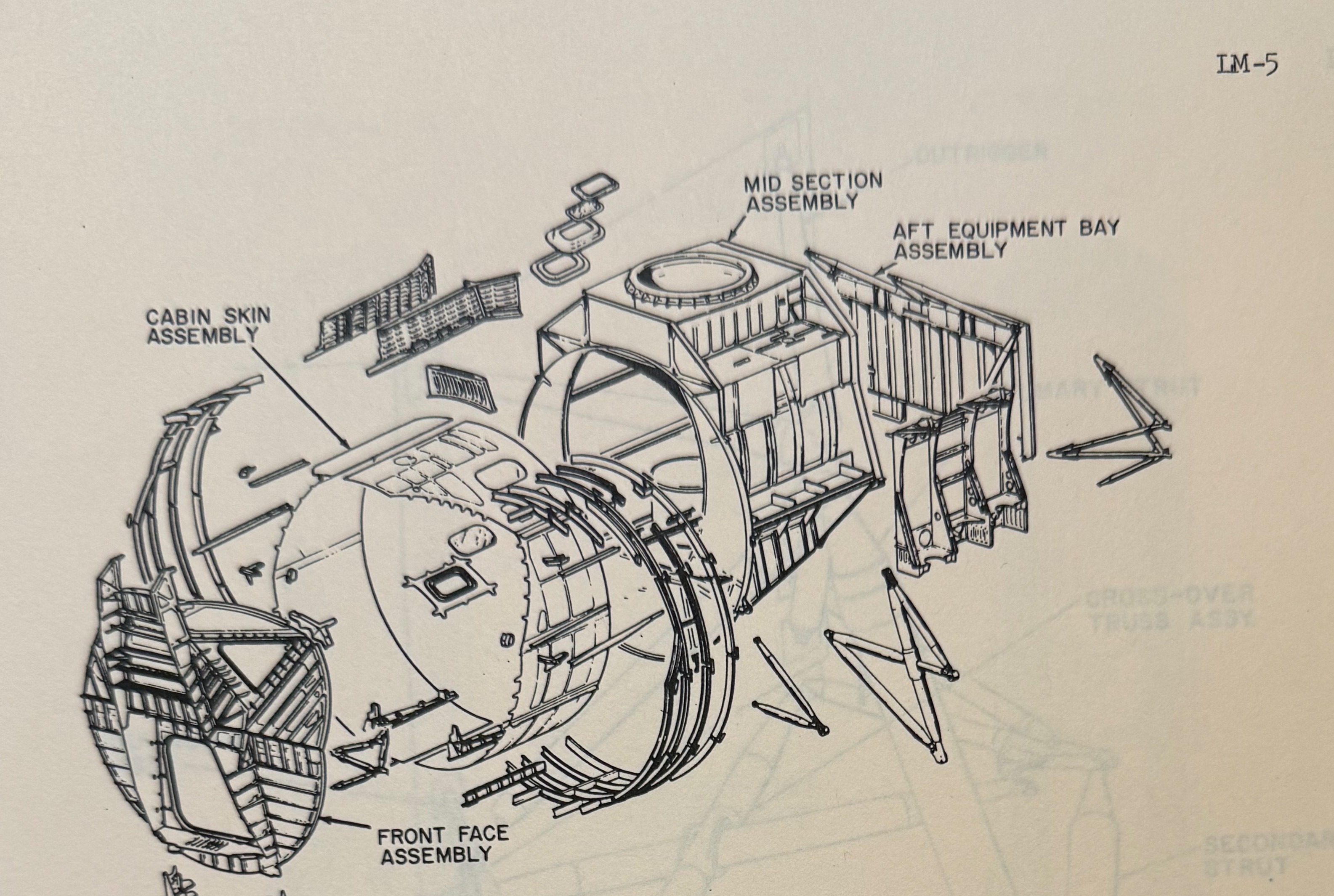
Where the EPS guide is about what keeps the Lunar Module powered, this one is about what the Lunar Module physically is and what an astronaut does with it on the ground. Chapter 1 works through the airframe — the ascent and descent stage structural assemblies shown here, the landing gear’s strut and downlock mechanism, thermal shielding and micrometeoroid protection, and the antenna erection mechanisms used during a moonwalk. Chapter 2 turns to the equipment astronauts would actually deploy on the surface: the descent stage’s Modularized Equipment Stowage Assembly and its primary and back-up deployment sequences, the Early Apollo Scientific Experiments Package, the S-band erectable antenna, the TV camera and tripod, and lunar sample-return gear, illustrated with two large fold-out diagrams of the Scientific Equipment Bay door mechanism.
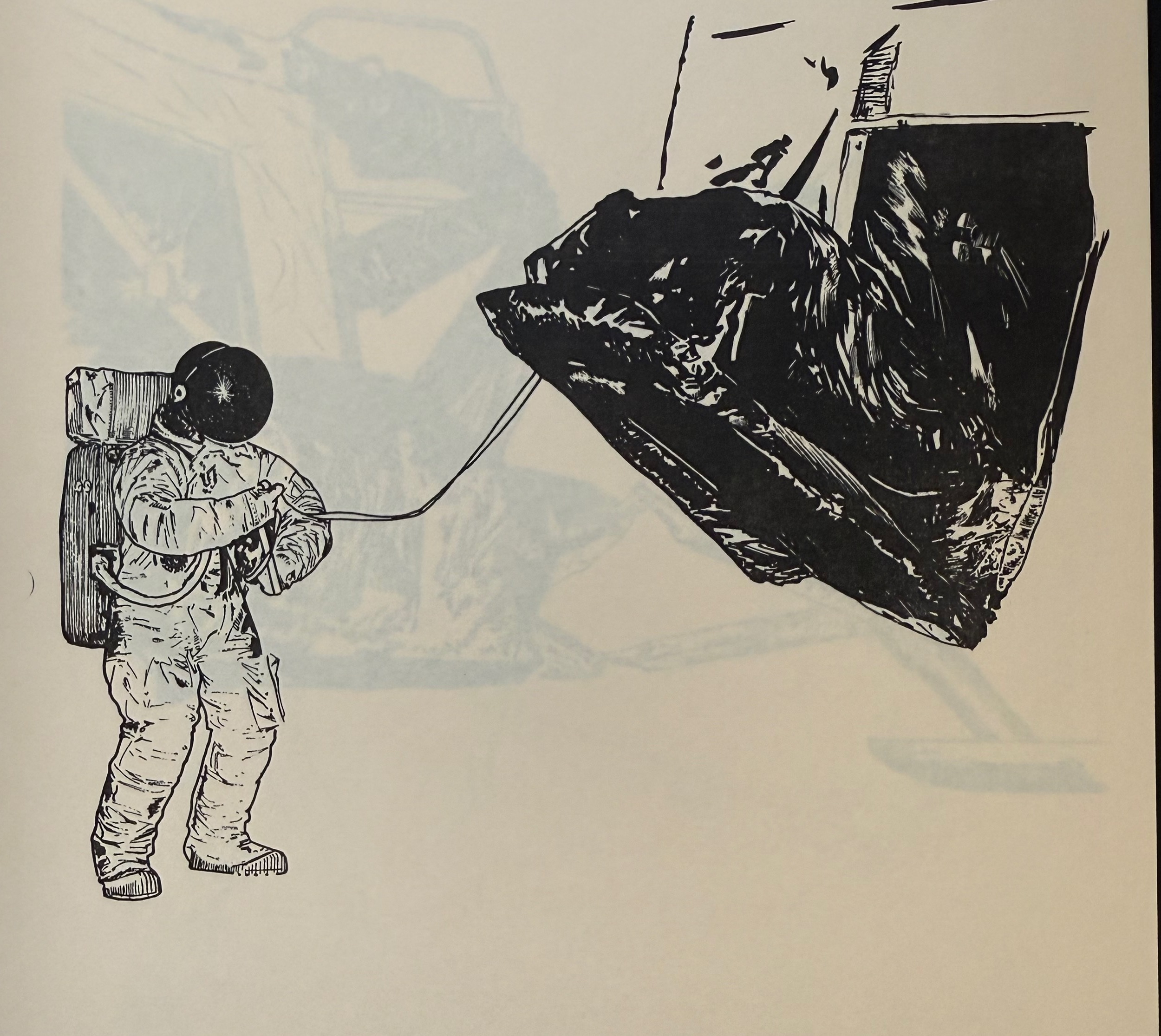
One illustration in particular reads differently once you know the date. If the Modularized Equipment Stowage Assembly — the pallet holding the surface experiments, sample containers, and the television camera that would broadcast the first steps — failed to open on its own, this handout shows the back-up: an astronaut in a pressure suit, standing beside the lander, hauling it open by a lanyard. It is a contingency procedure, not a moment from the mission record, but it was drawn for LM-5 two months before Armstrong and Aldrin stood on that same descent stage, and it is a reminder of how much of the Apollo 11 moonwalk had already been rehearsed, on paper, as something that might have to be done the hard way.